3. Apple II Graphics#
Hi-res graphics on the Apple II is odd. Graphics are memory-mapped, not exactly consecutively, and bits don't always correspond to pixels. Color especially is odd, compared to today's luxurious 32-bit per pixel RGBA.
The Apple II has two hi-res graphics pages, and maps the area from $2000-$3FFF to
high-res graphics page 1 (HGR1), and $4000-$5FFF to page 2 (HGR2).
We have routines to clear these screens.
    ORG     $7A51
CLEAR_HGR1:
    SUBROUTINE

    LDA     #$20                ; Start at $2000
    LDX     #$40                ; End at $4000 (but not including)
    BNE     CLEAR_PAGE          ; Unconditional jump

CLEAR_HGR2:
    SUBROUTINE

    LDA     #$40                ; Start at $4000
    LDX     #$60                ; End at $6000 (but not including)
    ; fallthrough

CLEAR_PAGE:
    STA     TMP_PTR+1           ; Start with the page in A.
    LDA     #$00
    STA     TMP_PTR
    TAY
    LDA     #$80                ; fill byte = 0x80

.loop:
    STA     (TMP_PTR),Y
    INY
    BNE     .loop
    INC     TMP_PTR+1
    CPX     TMP_PTR+1
    BNE     .loop               ; while TMP_PTR != X * 0x100
    RTS
3.1 Pixels and their color#
First we'll talk about pixels. Nominally, the resolution of the hi-res graphics screen is 280 pixels wide by 192 pixels tall. In the memory map, each row is represented by 40 bytes. The high bit of each byte is not used for pixel data, but is used to control color.
Here are some rules for how these bytes are turned into pixels:
- Pixels are drawn to the screen from byte data least significant bit first. This means that for the first byte bit 0 is column 0, bit 1 is column 1, and so on.
- A pattern of
11results in two white pixels at the1positions. - A pattern of
010results at least in a colored pixel at the1position. - A pattern of
101results at least in a colored pixel at the0position. - So, a pattern of
01010results in at least three consecutive colored pixels starting from the first1to the last1. The last0bit would also be colored if followed by a1. - Likewise, a pattern of
11011results in two white pixels, a colored pixel, and then two more white pixels. - The color of a
010pixel depends on the column that the1falls on, and also whether the high bit of its byte was set or not. - The color of a
11011pixel depends on the column that the0falls on, and also whether the high bit of its byte was set or not.
| Odd | Even | |
|---|---|---|
| High bit clear | Green | Violet |
| High bit set | Orange | Blue |
The implication is that you can only select one pair of colors per byte.
An example would probably be good here. We will take one of the sprites from the game.
| Bytes | Bits | Pixel Data |
|---|---|---|
00 00 |
0000000 0000000 |
00000000000000 |
00 00 |
0000000 0000000 |
00000000000000 |
00 00 |
0000000 0000000 |
00000000000000 |
55 00 |
1010101 0000000 |
10101010000000 |
41 00 |
1000001 0000000 |
10000010000000 |
01 00 |
0000001 0000000 |
10000000000000 |
55 00 |
1010101 0000000 |
10101010000000 |
50 00 |
1010000 0000000 |
00001010000000 |
50 00 |
1010000 0000000 |
00001010000000 |
51 00 |
1010001 0000000 |
10001010000000 |
55 00 |
1010101 0000000 |
10101010000000 |
The game automatically sets the high bit of each byte, so we know we're going to see orange and blue. Assuming that the following bits are all zero, and we place the sprite starting at column 0, we should see this:
| 0 | ||||||||||||||
| 1 | ||||||||||||||
| 2 | ||||||||||||||
| 3 | ||||||||||||||
| 4 | ||||||||||||||
| 5 | ||||||||||||||
| 6 | ||||||||||||||
| 7 | ||||||||||||||
| 8 | ||||||||||||||
| 9 | ||||||||||||||
| 10 |
Here is a more complex sprite:
| Bytes | Bits | Pixel Data |
|---|---|---|
40 00 |
1000000 0000000 |
00000010000000 |
60 01 |
1100000 0000001 |
00000111000000 |
60 01 |
1100000 0000001 |
00000111000000 |
70 00 |
1110000 0000000 |
00001110000000 |
6C 01 |
1101100 0000001 |
00110111000000 |
36 06 |
0110110 0000110 |
01101100110000 |
30 00 |
0110000 0000000 |
00001100000000 |
70 00 |
1110000 0000000 |
00001110000000 |
5E 01 |
1011110 0000001 |
01111011000000 |
40 01 |
1000000 0000001 |
00000011000000 |
40 01 |
1000000 0000001 |
00000011000000 |
| 0 | ||||||||||||||
| 1 | ||||||||||||||
| 2 | ||||||||||||||
| 3 | ||||||||||||||
| 4 | ||||||||||||||
| 5 | ||||||||||||||
| 6 | ||||||||||||||
| 7 | ||||||||||||||
| 8 | ||||||||||||||
| 9 | ||||||||||||||
| 10 |
Take note of the orange and blue pixels. All the patterns noted in the rules above are used.
(
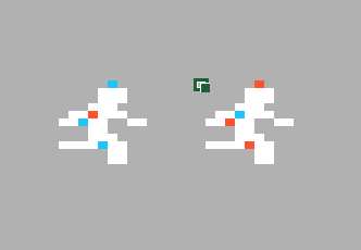
a2-lode-runner): This is sprite 9, the player (SPRITE_PLAYER); the first example is sprite 87, the letter S. Both are in the sprite catalog in the next section. Their colours are not stored in the sprite: they depend on whether a pixel lands on an odd or an even screen column. Moved by an odd number of columns, the same bytes show the dot on the player's head in orange instead of blue:
Rendered by a2-hires-lab, which shows black as grey. The small green square is the selected Excel cell: the top-left corner of the sprite's 14 by 11 area, where the right-hand player was placed. For how Apple II hi-res colour comes about, see Jeffrey Stanton, Apple Graphics & Arcade Game Design (The Book Company, 1982), and the colour model in
a2-hires-lab.
3.2 The sprites#
Lode Runner defines 104 sprites, each being 11 rows, with two bytes per row. The first bytes of all 104 sprites are in the table first, then the second bytes, then the third bytes, and so on. Later we will see that only the leftmost 10 pixels out of the 14-pixel description is used.
    ORG     $AD00
SPRITE_DATA:
    INCLUDE "sprite_data.asm"
SPRITE_EMPTY        EQU     #$00
SPRITE_BRICK        EQU     #$01
SPRITE_STONE        EQU     #$02
SPRITE_LADDER       EQU     #$03
SPRITE_ROPE         EQU     #$04
SPRITE_TRAP         EQU     #$05
SPRITE_INVISIBLE_LADDER       EQU     #$06
SPRITE_GOLD         EQU     #$07
SPRITE_GUARD        EQU     #$08
SPRITE_PLAYER       EQU     #$09
SPRITE_ALLWHITE     EQU     #$0A
SPRITE_BRICK_FILL0  EQU     #$37
SPRITE_BRICK_FILL1  EQU     #$38
SPRITE_GUARD_EGG0   EQU     #$39
SPRITE_GUARD_EGG1   EQU     #$3A
(
a2-lode-runner): Why this order? The 6502 has no multiply instruction. If each sprite's 22 bytes were stored together, finding a sprite would take a multiplication by 22 on every draw. In this layout the sprite number is itself the index: the table is 22 blocks of 104 bytes, one block per byte position, soLDA (TMP_PTR),YwithYset to the sprite number reads that sprite's byte, and the next byte of the same sprite is always 104 ($68) bytes further on.COMPUTE_SHIFTED_SPRITEin the next section works exactly like this.To see which pixel of a sprite belongs to which bit of which byte, a2-hires-lab loads a sprite by its number into the
Sprite (load)sheet, with pixels, bytes, bits and colours side by side.
3.3 Shifting sprites#
This is all very good if we're going to draw sprites exactly on 7-pixel boundaries, but what if we want to draw them starting at other columns? In general, such a shifted sprite would straddle three bytes, and Lode Runner sets aside an area of memory at the end of zero page for 11 rows of three bytes that we'll write to when we want to compute the data for a shifted sprite.
BLOCK_DATA EQU $DF ; 33 bytes
Lode Runner also contains tables which show how to shift any arbitrary 7-pixel pattern right by any amount from zero to six pixels.
For example, suppose we start with a pixel pattern of 0110001, and we want to
shift that right by three bits. The 14-bit result would be 0000110 0010000.
However, we have to break that up into bytes, reverse the bits (remember that
each byte's bits are output as pixels least significant bit first), and set
their high bits, so we end up with 10110000 10000100.
Now, given a shift amount and a pixel pattern, we should be able to find the two-byte shifted pattern. Lode Runner accomplishes this with table lookups as follows:
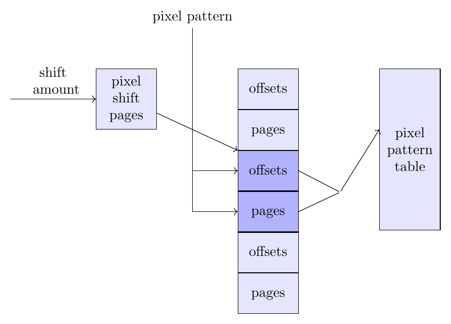
The pixel pattern table is a table of every possible pattern of 7 consecutive pixels
spread out over two bytes. This table is 512 entries, each entry being two bytes.
A naive table would have redundancy. For example the pattern 0000100 starting
at column 0 is exactly the same as the pattern 0001000 starting at column 1.
This table eliminates that redundancy.
    ORG     $A900
PIXEL_PATTERN_TABLE:
    INCLUDE "pixel_pattern_table.asm"
Now we just need tables which index into PIXEL_PATTERN_TABLE for every
7-pixel pattern and shift value. This table works by having the page number
for the shifted pixel pattern at index shift * 0x100 + 0x80 + pattern
and the offset at index shift * 0x100 + pattern.
    ORG     $A200
PIXEL_SHIFT_TABLE:
    INCLUDE "pixel_shift_table.asm"
Rather than multiplying the shift value by 0x100, we instead define
another table which holds the page numbers for the shift tables for each
shift value.
    ORG     $84C1
PIXEL_SHIFT_PAGES:
    HEX     A2 A3 A4 A5 A6 A7 A8
So we can get shifted pixels by indexing into all these tables.
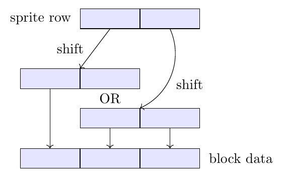
Now we can define a routine that will take a sprite number and a pixel shift
amount, and write the shifted pixel data into the BLOCK_DATA area. The
routine first shifts the first byte of the sprite into a two-byte area. Then
it shifts the second byte of the sprite, and combines that two-byte result
with the first. Thus, we shift two bytes of sprite data into a three-byte
result.
Rather than load addresses from the tables and store them, the routine modifies its own instructions with those addresses.
ROW_COUNT       EQU     $1D
SPRITE_NUM      EQU     $1E
    ORG     $8438
COMPUTE_SHIFTED_SPRITE:
    SUBROUTINE
    ; Enter routine with X set to pixel shift amount and
    ; SPRITE_NUM containing the sprite number to read.

.offset_table       EQU $A000               ; Target addresses in read
.page_table         EQU $A080               ; instructions. The only truly
.shift_ptr_byte0    EQU $A000               ; necessary value here is the
.shift_ptr_byte1    EQU $A000               ; 0x80 in .shift_ptr_byte0.

    LDA     #$0B                            ; 11 rows
    STA     ROW_COUNT
    LDA     #<SPRITE_DATA
    STA     TMP_PTR
    LDA     #>SPRITE_DATA
    STA     TMP_PTR+1                       ; TMP_PTR = SPRITE_DATA
    LDA     PIXEL_SHIFT_PAGES,X
    STA     .rd_offset_table + 2
    STA     .rd_page_table + 2
    STA     .rd_offset_table2 + 2
    STA     .rd_page_table2 + 2             ; Fix up pages in lookup instructions
                                            ; based on shift amount (X).

    LDX     #$00                            ; X is the offset into BLOCK_DATA.

.loop:                                      ; === LOOP === (over all 11 rows)
    LDY     SPRITE_NUM
    LDA     (TMP_PTR),Y
    TAY                                     ; Get sprite pixel data.

.rd_offset_table:
    LDA     .offset_table,Y                 ; Load offset for shift amount.
    STA     .rd_shift_ptr_byte0 + 1
    CLC
    ADC     #$01
    STA     .rd_shift_ptr_byte1 + 1         ; Fix up instruction offsets with it.
.rd_page_table:
    LDA     .page_table,Y                   ; Load page for shift amount.
    STA     .rd_shift_ptr_byte0 + 2
    STA     .rd_shift_ptr_byte1 + 2         ; Fix up instruction page with it.

.rd_shift_ptr_byte0:
    LDA     .shift_ptr_byte0                ; Read shifted pixel data byte 0
    STA     BLOCK_DATA,X                    ; and store in block data byte 0.
.rd_shift_ptr_byte1:
    LDA     .shift_ptr_byte1                ; Read shifted pixel data byte 1
    STA     BLOCK_DATA+1,X                  ; and store in block data byte 1.

    LDA     TMP_PTR
    CLC
    ADC     #$68
    STA     TMP_PTR
    LDA     TMP_PTR+1
    ADC     #$00
    STA     TMP_PTR+1                       ; TMP_PTR++

    ; Now basically do the same thing with the second sprite byte

    LDY     SPRITE_NUM
    LDA     (TMP_PTR),Y
    TAY                                     ; Get sprite pixel data.

.rd_offset_table2:
    LDA     .offset_table,Y                 ; Load offset for shift amount.
    STA     .rd_shift_ptr2_byte0 + 1
    CLC
    ADC     #$01
    STA     .rd_shift_ptr2_byte1 + 1        ; Fix up instruction offsets with it.
.rd_page_table2:
    LDA     .page_table,Y                   ; Load page for shift amount.
    STA     .rd_shift_ptr2_byte0 + 2
    STA     .rd_shift_ptr2_byte1 + 2        ; Fix up instruction page with it.

.rd_shift_ptr2_byte0:
    LDA     .shift_ptr_byte0                ; Read shifted pixel data byte 0
    ORA     BLOCK_DATA+1,X                  ; OR with previous block data byte 1
    STA     BLOCK_DATA+1,X                  ; and store in block data byte 1.
.rd_shift_ptr2_byte1:
    LDA     .shift_ptr_byte1                ; Read shifted pixel data byte 1
    STA     BLOCK_DATA+2,X                  ; and store in block data byte 2.

    LDA     TMP_PTR
    CLC
    ADC     #$68
    STA     TMP_PTR
    LDA     TMP_PTR+1
    ADC     #$00
    STA     TMP_PTR+1                       ; TMP_PTR++

    INX
    INX
    INX                                     ; X += 3
    DEC     ROW_COUNT                       ; ROW_COUNT--
    BNE     .loop                           ; loop while ROW_COUNT > 0
    RTS
COMPUTE_SHIFTED_SPRITE(
a2-lode-runner): A smaller and faster table. As built, each sprite byte goes through two tables. Its 7-bit patternYindexes the shift table page for the shift amount, which yields the address of a two-byte entry inPIXEL_PATTERN_TABLE; the routine writes that address into its ownLDAinstructions and then reads the two result bytes. For pattern$16(%0010110) shifted by 3:flowchart LR S["shift 3"] -->|"PIXEL_SHIFT_PAGES"| P["page $A5"] Y["pattern $16"] --> LO Y --> HI P -->|"$A500 + $16"| LO["offset $5A"] P -->|"$A580 + $16"| HI["page $A9"] LO --> A["address $A95A<br/>in PIXEL_PATTERN_TABLE"] HI --> A A --> B["bytes $B0 $81"]There are only 128 patterns times 7 shift amounts, 896 cases of two bytes each. A table holding those result bytes directly needs 896 x 2 = 1,792 bytes: exactly the size of
PIXEL_SHIFT_TABLEalone, with byte 0 in the first half of each page and byte 1 in the second half, where the offsets and pages sit now. The lookup then becomes two plain reads, and the per-byte patching disappears:LDA $A200,Y ; page patched to $A2 + shift once per sprite -> byte 0 STA BLOCK_DATA,X LDA $A280,Y ; same page, second half -> byte 1 STA BLOCK_DATA+1,XThis would save the 1,024 bytes of
PIXEL_PATTERN_TABLEand 56 of the 162 cycles per sprite row: 1,208 instead of 1,824 cycles for the whole routine, a third less. (Counted with the standard 6502 timings, including theRTS; the occasional extra cycle when(TMP_PTR),Ycrosses a page is the same in both versions.) The two tables were checked against direct shifting for all 896 cases, and all 512 pattern entries are used. The check runs as a test in a2-hires-lab, whosePixel ShifterandSprite Shiftersheets follow both lookups step by step.Reducing 896 cases to 512 unique patterns looks like a saving, but the two-byte pointers to them cost as much as the result bytes themselves. Why the game uses two tables anyway is not known.
Why
main.pdfsays "never used". Inmain.pdf, the notes under the definitions ofPIXEL_SHIFT_TABLEandPIXEL_PATTERN_TABLEsay "never used", although this routine reads both on every call. No instruction names them: the shift table is reached through the page numbers inPIXEL_SHIFT_PAGES, and the pattern table through addresses the routine writes into its own instructions. A cross-reference built from names cannot see accesses like these.
3.4 Memory mapped graphics#
Within a screen row, consecutive bytes map to consecutive pixels. However, rows themselves are not consecutive in memory.
To make it easy to convert a row number from 0 to 191 to a base address, Lode Runner has a table and a routine to use that table.
    ORG     $1A85
ROW_TO_OFFSET_LO:
    INCLUDE "row_to_offset_lo_table.asm"
ROW_TO_OFFSET_HI:
    INCLUDE "row_to_offset_hi_table.asm"
    ORG     $7A31
ROW_TO_ADDR:
    SUBROUTINE
    ; Enter routine with Y set to row. Base address
    ; (for column 0) will be placed in ROW_ADDR.

    LDA     ROW_TO_OFFSET_LO,Y
    STA     ROW_ADDR
    LDA     ROW_TO_OFFSET_HI,Y
    ORA     HGR_PAGE
    STA     ROW_ADDR+1
    RTS
ROW_TO_ADDRThere's also a routine to load the address for both page 1 and page 2.
    ORG     $7A3E
ROW_TO_ADDR_FOR_BOTH_PAGES:
    SUBROUTINE
    ; Enter routine with Y set to row. Base address
    ; (for column 0) will be placed in ROW_ADDR (for page 1)
    ; and ROW_ADDR2 (for page 2).

    LDA     ROW_TO_OFFSET_LO,Y
    STA     ROW_ADDR
    STA     ROW_ADDR2
    LDA     ROW_TO_OFFSET_HI,Y
    ORA     #$20
    STA     ROW_ADDR+1
    EOR     #$60
    STA     ROW_ADDR2+1
    RTS
ROW_TO_ADDR_FOR_BOTH_PAGESLode Runner's screens are organized into 28 sprites across by 17 sprites down. To convert between sprite coordinates and screen coordinates and vice-versa, we use tables and lookup routines. Each sprite is 10 pixels across by 11 pixels down.
Note that the last row is used for the status, so actually the game screen is 16 sprites vertically.
MAX_GAME_COL        EQU     #27     ; 0x1B
MAX_GAME_ROW        EQU     #15     ; 0x0F
    ORG     $1C35
HALF_SCREEN_COL_TABLE:
    ; 28 cols of 5 double-pixels each
    HEX     00 05 0a 0f 14 19 1e 23 28 2d 32 37 3c 41 46 4b
    HEX     50 55 5a 5f 64 69 6e 73 78 7d 82 87
SCREEN_ROW_TABLE:
    ; 17 rows of 11 pixels each
    HEX     00 0B 16 21 2C 37 42 4D 58 63 6E 79 84 8F 9A A5
    HEX     B5
COL_BYTE_TABLE:
    ; Byte number
    HEX     00 01 02 04 05 07 08 0A 0B 0C 0E 0F 11 12 14 15
    HEX     16 18 19 1B 1C 1E 1F 20 22 23 25 26
COL_SHIFT_TABLE:
    ; Right shift amount
    HEX     00 03 06 02 05 01 04 00 03 06 02 05 01 04 00 03
    HEX     06 02 05 01 04 00 03 06 02 05 01 04
HALF_SCREEN_COL_BYTE_TABLE:
    HEX     00 00 00 00 01 01 01 02 02 02 02 03 03 03 04 04
    HEX     04 04 05 05 05 06 06 06 06 07 07 07 08 08 08 08
    HEX     09 09 09 0A 0A 0A 0A 0B 0B 0B 0C 0C 0C 0C 0D 0D
    HEX     0D 0E 0E 0E 0E 0F 0F 0F 10 10 10 10 11 11 11 12
    HEX     12 12 12 13 13 13 14 14 14 14 15 15 15 16 16 16
    HEX     16 17 17 17 18 18 18 18 19 19 19 1A 1A 1A 1A 1B
    HEX     1B 1B 1C 1C 1C 1C 1D 1D 1D 1E 1E 1E 1E 1F 1F 1F
    HEX     20 20 20 20 21 21 21 22 22 22 22 23 23 23 24 24
    HEX     24 24 25 25 25 26 26 26 26 27 27 27
HALF_SCREEN_COL_SHIFT_TABLE:
    HEX     00 02 04 06 01 03 05 00 02 04 06 01 03 05 00 02
    HEX     04 06 01 03 05 00 02 04 06 01 03 05 00 02 04 06
    HEX     01 03 05 00 02 04 06 01 03 05 00 02 04 06 01 03
    HEX     05 00 02 04 06 01 03 05 00 02 04 06 01 03 05 00
    HEX     02 04 06 01 03 05 00 02 04 06 01 03 05 00 02 04
    HEX     06 01 03 05 00 02 04 06 01 03 05 00 02 04 06 01
    HEX     03 05 00 02 04 06 01 03 05 00 02 04 06 01 03 05
    HEX     00 02 04 06 01 03 05 00 02 04 06 01 03 05 00 02
    HEX     04 06 01 03 05 00 02 04 06 01 03 05
Here is the routine to return the screen coordinates for the given sprite coordinates.
The reason that GET_SCREEN_COORDS_FOR returns half the screen column coordinate
is that otherwise the screen column coordinate wouldn't fit in a register.
    ORG     $885D
GET_SCREEN_COORDS_FOR:
    SUBROUTINE
    ; Enter routine with Y set to sprite row (0-16) and
    ; X set to sprite column (0-27). On return, Y will be set to
    ; screen row, and X is set to half screen column.

    LDA     SCREEN_ROW_TABLE,Y
    PHA
    LDA     HALF_SCREEN_COL_TABLE,X
    TAX                         ; X = HALF_SCREEN_COL_TABLE[X]
    PLA
    TAY                         ; Y = SCREEN_ROW_TABLE[Y]
    RTS
This routine takes a sprite column and converts it to the memory-mapped byte offset and right-shift amount.
    ORG     $8868
GET_BYTE_AND_SHIFT_FOR_COL:
    SUBROUTINE
    ; Enter routine with X set to sprite column. On
    ; return, A will be set to screen column byte number
    ; and X will be set to an additional right shift amount.

    LDA     COL_BYTE_TABLE,X
    PHA                         ; A = COL_BYTE_TABLE[X]
    LDA     COL_SHIFT_TABLE,X
    TAX                         ; X = COL_SHIFT_TABLE[X]
    PLA
    RTS
This routine takes half the screen column coordinate and converts it to the memory-mapped byte offset and right-shift amount.
    ORG     $8872
GET_BYTE_AND_SHIFT_FOR_HALF_SCREEN_COL:
    SUBROUTINE
    ; Enter routine with X set to half screen column. On
    ; return, A will be set to screen column byte number
    ; and X will be set to an additional right shift amount.

    LDA     HALF_SCREEN_COL_BYTE_TABLE,X
    PHA                         ; A = HALF_SCREEN_COL_BYTE_TABLE[X]
    LDA     HALF_SCREEN_COL_SHIFT_TABLE,X
    TAX                         ; X = HALF_SCREEN_COL_SHIFT_TABLE[X]
    PLA
    RTS
GET_BYTE_AND_SHIFT_FOR_HALF_SCREEN_COLWe also have some utility routines that let us take a sprite row or column and
get its screen row or half column, but offset in either row or column by anywhere from
-2 to +2.
    ORG     $888A
ROW_OFFSET_TABLE:
    HEX     FB FD 00 02 04
    ORG     $887C
GET_SCREEN_ROW_OFFSET_IN_X_FOR:
    SUBROUTINE
    ; Enter routine with X set to offset+2 (in double-pixels) and
    ; Y set to sprite row. On return, X will retain its value and
    ; Y will be set to the screen row.

    TXA
    PHA
    JSR     GET_SCREEN_COORDS_FOR
    PLA
    TAX                                 ; Restore X
    TYA
    CLC
    ADC     ROW_OFFSET_TABLE,X
    TAY
    RTS
GET_SCREEN_ROW_OFFSET_IN_X_FORORG $889D COL_OFFSET_TABLE: HEX FE FF 00 01 02
    ORG     $888F
GET_HALF_SCREEN_COL_OFFSET_IN_Y_FOR:
    SUBROUTINE
    ; Enter routine with Y set to offset+2 (in double-pixels) and
    ; X set to sprite column. On return, Y will retain its value and
    ; X will be set to the half screen column.

    TYA
    PHA
    JSR     GET_SCREEN_COORDS_FOR
    PLA
    TAY                                 ; Restore Y
    TXA
    CLC
    ADC     COL_OFFSET_TABLE,Y
    TAX
    RTS
GET_HALF_SCREEN_COL_OFFSET_IN_Y_FORNow we can finally write the routines that draw a sprite on the screen. We have one routine that draws a sprite at a given game row and game column. There are two entry points, one to draw on HGR1, and one for HGR2.
ROWNUM          EQU     $1B
COLNUM          EQU     $1C
MASK0           EQU     $50
MASK1           EQU     $51
COL_SHIFT_AMT   EQU     $71
GAME_COLNUM     EQU     $85
GAME_ROWNUM     EQU     $86
    ORG     $8328
PIXEL_MASK0:
    BYTE    %00000000
    BYTE    %00000001
    BYTE    %00000011
    BYTE    %00000111
    BYTE    %00001111
    BYTE    %00011111
    BYTE    %00111111
PIXEL_MASK1:
    BYTE    %11111000
    BYTE    %11110000
    BYTE    %11100000
    BYTE    %11000000
    BYTE    %10000000
    BYTE    %11111110
    BYTE    %11111100
    ORG     $82AA
DRAW_SPRITE_PAGE1:
    SUBROUTINE
    ; Enter routine with A set to sprite number to draw,
    ; GAME_ROWNUM set to the row to draw it at, and GAME_COLNUM
    ; set to the column to draw it at.

    STA     SPRITE_NUM
    LDA     #$20                ; Page number for HGR1
    BNE     DRAW_SPRITE         ; Actually unconditional jump

DRAW_SPRITE_PAGE2:
    SUBROUTINE
    ; Enter routine with A set to sprite number to draw,
    ; GAME_ROWNUM set to the row to draw it at, and GAME_COLNUM
    ; set to the column to draw it at.

    STA     SPRITE_NUM
    LDA     #$40                ; Page number for HGR2
    ; fallthrough

DRAW_SPRITE:
    STA     HGR_PAGE
    LDY     GAME_ROWNUM
    JSR     GET_SCREEN_COORDS_FOR
    STY     ROWNUM              ; ROWNUM = SCREEN_ROW_TABLE[GAME_ROWNUM]

    LDX     GAME_COLNUM
    JSR     GET_BYTE_AND_SHIFT_FOR_COL
    STA     COLNUM              ; COLNUM = COL_BYTE_TABLE[GAME_COLNUM]
    STX     COL_SHIFT_AMT       ; COL_SHIFT_AMT = COL_SHIFT_TABLE[GAME_COLNUM]

    LDA     PIXEL_MASK0,X
    STA     MASK0               ; MASK0 = PIXEL_MASK0[COL_SHIFT_AMT]
    LDA     PIXEL_MASK1,X
    STA     MASK1               ; MASK1 = PIXEL_MASK1[COL_SHIFT_AMT]

    JSR     COMPUTE_SHIFTED_SPRITE

    LDA     #$0B
    STA     ROW_COUNT
    LDX     #$00
    LDA     COL_SHIFT_AMT
    CMP     #$05
    BCS     .need_3_bytes       ; If COL_SHIFT_AMT >= 5, we need to alter three
                                ; screen bytes, otherwise just two bytes.

.loop1:
    LDY     ROWNUM
    JSR     ROW_TO_ADDR
    LDY     COLNUM
    LDA     (ROW_ADDR),Y
    AND     MASK0
    ORA     BLOCK_DATA,X
    STA     (ROW_ADDR),Y        ; screen[COLNUM] =
                                ;   screen[COLNUM] & MASK0 | BLOCK_DATA[i]

    INX                         ; X++
    INY                         ; Y++
    LDA     (ROW_ADDR),Y
    AND     MASK1
    ORA     BLOCK_DATA,X
    STA     (ROW_ADDR),Y        ; screen[COLNUM+1] =
                                ;   screen[COLNUM+1] & MASK1 | BLOCK_DATA[i+1]

    INX
    INX                         ; X += 2
    INC     ROWNUM              ; ROWNUM++
    DEC     ROW_COUNT           ; ROW_COUNT--
    BNE     .loop1              ; loop while ROW_COUNT > 0
    RTS

.need_3_bytes
    LDY     ROWNUM
    JSR     ROW_TO_ADDR
    LDY     COLNUM
    LDA     (ROW_ADDR),Y
    AND     MASK0
    ORA     BLOCK_DATA,X
    STA     (ROW_ADDR),Y        ; screen[COLNUM] =
                                ;   screen[COLNUM] & MASK0 | BLOCK_DATA[i]

    INX                         ; X++
    INY                         ; Y++
    LDA     BLOCK_DATA,X
    STA     (ROW_ADDR),Y        ; screen[COLNUM+1] = BLOCK_DATA[i+1]

    INX                         ; X++
    INY                         ; Y++
    LDA     (ROW_ADDR),Y
    AND     MASK1
    ORA     BLOCK_DATA,X
    STA     (ROW_ADDR),Y        ; screen[COLNUM+2] =
                                ;   screen[COLNUM+2] & MASK1 | BLOCK_DATA[i+2]

    INX                         ; X++
    INC     ROWNUM              ; ROWNUM++
    DEC     ROW_COUNT           ; ROW_COUNT--
    BNE     .need_3_bytes       ; loop while ROW_COUNT > 0
    RTS
DRAW_SPRITE_PAGE1, DRAW_SPRITE_PAGE2There is a different routine which erases a sprite at a given screen coordinate. It does this by drawing the inverse of the sprite on page 1, then drawing the sprite data from page 2 (the background page) onto page 1.
Upon entry, the Y register needs to be set to the screen row coordinate (0-191). However, the X register needs to be set to half the screen column coordinate (0-139) because otherwise the maximum coordinate (279) wouldn't fit in a register.
    ORG     $8336
ERASE_SPRITE_AT_PIXEL_COORDS:
    SUBROUTINE
    ; Enter routine with A set to sprite number to draw,
    ; Y set to the screen row to erase it at, and X
    ; set to *half* the screen column to erase it at.

    STY     ROWNUM
    STA     SPRITE_NUM
    JSR     GET_BYTE_AND_SHIFT_FOR_HALF_SCREEN_COL
    STA     COLNUM
    STX     COL_SHIFT_AMT
    JSR     COMPUTE_SHIFTED_SPRITE

    LDX     #$0B
    STX     ROW_COUNT
    LDX     #$00
    LDA     COL_SHIFT_AMT
    CMP     #$05
    BCS     .need_3_bytes       ; If COL_SHIFT_AMT >= 5, we need to alter three
                                ; screen bytes, otherwise just two bytes.

.loop1:
    LDY     ROWNUM
    JSR     ROW_TO_ADDR_FOR_BOTH_PAGES
    LDY     COLNUM
    LDA     BLOCK_DATA,X
    EOR     #$7F
    AND     (ROW_ADDR),Y
    ORA     (ROW_ADDR2),Y
    STA     (ROW_ADDR),Y            ; screen[COLNUM] =
                                    ;   (screen[COLNUM] & (BLOCK_DATA[i] ^ 0x7F)) |
                                    ;   screen2[COLNUM]

    INX                             ; X++
    INY                             ; Y++
    LDA     BLOCK_DATA,X
    EOR     #$7F
    AND     (ROW_ADDR),Y
    ORA     (ROW_ADDR2),Y
    STA     (ROW_ADDR),Y            ; screen[COLNUM+1] =
                                    ;   (screen[COLNUM+1] & (BLOCK_DATA[i+1] ^ 0x7F)) |
                                    ;   screen2[COLNUM+1]

    INX                             ; X++
    INX                             ; X++
    INC     ROWNUM
    DEC     ROW_COUNT
    BNE     .loop1
    RTS

.need_3_bytes:
    LDY     ROWNUM
    JSR     ROW_TO_ADDR_FOR_BOTH_PAGES
    LDY     COLNUM
    LDA     BLOCK_DATA,X
    EOR     #$7F
    AND     (ROW_ADDR),Y
    ORA     (ROW_ADDR2),Y
    STA     (ROW_ADDR),Y            ; screen[COLNUM] =
                                    ;   (screen[COLNUM] & (BLOCK_DATA[i] ^ 0x7F)) |
                                    ;   screen2[COLNUM]

    INX                             ; X++
    INY                             ; Y++
    LDA     BLOCK_DATA,X
    EOR     #$7F
    AND     (ROW_ADDR),Y
    ORA     (ROW_ADDR2),Y
    STA     (ROW_ADDR),Y            ; screen[COLNUM+1] =
                                    ;   (screen[COLNUM+1] & (BLOCK_DATA[i+1] ^ 0x7F)) |
                                    ;   screen2[COLNUM+1]

    INX                             ; X++
    INY                             ; Y++
    LDA     BLOCK_DATA,X
    EOR     #$7F
    AND     (ROW_ADDR),Y
    ORA     (ROW_ADDR2),Y
    STA     (ROW_ADDR),Y            ; screen[COLNUM+2] =
                                    ;   (screen[COLNUM+2] & (BLOCK_DATA[i+2] ^ 0x7F)) |
                                    ;   screen2[COLNUM+2]

    INX                             ; X++
    INC     ROWNUM
    DEC     ROW_COUNT
    BNE     .need_3_bytes
    RTS
ERASE_SPRITE_AT_PIXEL_COORDSAnd then there's the corresponding routine to draw a sprite at the given coordinates. The
routine also sets whether the active and the background screens differ in SCREENS_DIFFER.
SCREENS_DIFFER EQU $52
    ORG     $83A7
DRAW_SPRITE_AT_PIXEL_COORDS:
    SUBROUTINE
    ; Enter routine with A set to sprite number to draw,
    ; Y set to the screen row to draw it at, and X
    ; set to *half* the screen column to draw it at.

    STY     ROWNUM
    STA     SPRITE_NUM
    JSR     GET_BYTE_AND_SHIFT_FOR_HALF_SCREEN_COL
    STA     COLNUM
    STX     COL_SHIFT_AMT
    JSR     COMPUTE_SHIFTED_SPRITE

    LDA     #$0B
    STA     ROW_COUNT
    LDX     #$00
    STX     SCREENS_DIFFER      ; SCREENS_DIFFER = 0
    LDA     COL_SHIFT_AMT
    CMP     #$05
    BCS     .need_3_bytes       ; If COL_SHIFT_AMT >= 5, we need to alter three
                                ; screen bytes, otherwise just two bytes.

.loop1:
    LDY     ROWNUM
    JSR     ROW_TO_ADDR_FOR_BOTH_PAGES
    LDY     COLNUM
    LDA     (ROW_ADDR),Y
    EOR     (ROW_ADDR2),Y
    AND     BLOCK_DATA,X
    ORA     SCREENS_DIFFER
    STA     SCREENS_DIFFER          ; SCREENS_DIFFER |=
                                    ;   ( (screen[COLNUM] ^ screen2[COLNUM]) &
                                    ;     BLOCK_DATA[i])
    LDA     BLOCK_DATA,X
    ORA     (ROW_ADDR),Y
    STA     (ROW_ADDR),Y            ; screen[COLNUM] |= BLOCK_DATA[i]

    INX                             ; X++
    INY                             ; Y++
    LDA     (ROW_ADDR),Y
    EOR     (ROW_ADDR2),Y
    AND     BLOCK_DATA,X
    ORA     SCREENS_DIFFER
    STA     SCREENS_DIFFER          ; SCREENS_DIFFER |=
                                    ;   ( (screen[COLNUM+1] ^ screen2[COLNUM+1]) &
                                    ;     BLOCK_DATA[i+1])
    LDA     BLOCK_DATA,X
    ORA     (ROW_ADDR),Y
    STA     (ROW_ADDR),Y            ; screen[COLNUM+1] |= BLOCK_DATA[i+1]

    INX                             ; X++
    INX                             ; X++
    INC     ROWNUM
    DEC     ROW_COUNT
    BNE     .loop1
    RTS

.need_3_bytes:
    LDY     ROWNUM
    JSR     ROW_TO_ADDR_FOR_BOTH_PAGES
    LDY     COLNUM
    LDA     (ROW_ADDR),Y
    EOR     (ROW_ADDR2),Y
    AND     BLOCK_DATA,X
    ORA     SCREENS_DIFFER
    STA     SCREENS_DIFFER          ; SCREENS_DIFFER |=
                                    ;   ( (screen[COLNUM] ^ screen2[COLNUM]) &
                                    ;     BLOCK_DATA[i])
    LDA     BLOCK_DATA,X
    ORA     (ROW_ADDR),Y
    STA     (ROW_ADDR),Y            ; screen[COLNUM] |= BLOCK_DATA[i]

    INX                             ; X++
    INY                             ; Y++
    LDA     (ROW_ADDR),Y
    EOR     (ROW_ADDR2),Y
    AND     BLOCK_DATA,X
    ORA     SCREENS_DIFFER
    STA     SCREENS_DIFFER          ; SCREENS_DIFFER |=
                                    ;   ( (screen[COLNUM+1] ^ screen2[COLNUM+1]) &
                                    ;     BLOCK_DATA[i+1])
    LDA     BLOCK_DATA,X
    ORA     (ROW_ADDR),Y
    STA     (ROW_ADDR),Y            ; screen[COLNUM+1] |= BLOCK_DATA[i+1]

    INX                             ; X++
    INY                             ; Y++
    LDA     (ROW_ADDR),Y
    EOR     (ROW_ADDR2),Y
    AND     BLOCK_DATA,X
    ORA     SCREENS_DIFFER
    STA     SCREENS_DIFFER          ; SCREENS_DIFFER |=
                                    ;   ( (screen[COLNUM+2] ^ screen2[COLNUM+2]) &
                                    ;     BLOCK_DATA[i+2])
    LDA     BLOCK_DATA,X
    ORA     (ROW_ADDR),Y
    STA     (ROW_ADDR),Y            ; screen[COLNUM+2] |= BLOCK_DATA[i+2]

    INX                             ; X++
    INC     ROWNUM
    DEC     ROW_COUNT
    BNE     .need_3_bytes
    RTS
DRAW_SPRITE_AT_PIXEL_COORDSThere is a special routine to draw the player sprite at the player's location. If the two pages at the player's location are different and the player didn't pick up gold (which would explain the difference), then the player is killed.
    ORG     $6C02
DRAW_PLAYER:
    SUBROUTINE

    JSR     GET_SPRITE_AND_SCREEN_COORD_AT_PLAYER
    JSR     DRAW_SPRITE_AT_PIXEL_COORDS
    LDA     SCREENS_DIFFER
    BEQ     .end
    LDA     DIDNT_PICK_UP_GOLD
    BEQ     .end
    LSR     ALIVE       ; Set player as dead
.end
    RTS
DRAW_PLAYER3.5 Printing strings#
Now that we can put sprites onto the screen at any game coordinate, we can also have some routines that print strings. We saw above that we have letter and number sprites, plus some punctuation. Letters and punctuation are always blue, while numbers are always orange.
There is a basic routine to put a character at the current GAME_COLNUM
and GAME_ROWNUM, incrementing this "cursor", and putting it at the beginning
of the next line if we "print" a newline character.
We first define a routine to convert the ASCII code of a character to its sprite number. Lode Runner sets the high bit of the code to make it be treated as ASCII.
    ORG     $7B2A
CHAR_TO_SPRITE_NUM:
    SUBROUTINE
    ; Enter routine with A set to the ASCII code of the
    ; character to convert to sprite number, with the high bit set.
    ; The sprite number is returned in A.

    CMP     #$C1                    ; 'A' -> sprite 69
    BCC     .not_letter
    CMP     #$DB                    ; 'Z' -> sprite 94
    BCC     .letter

.not_letter:
    ; On return, we will subtract 0x7C from X to
    ; get the actual sprite. This is to make A-Z
    ; easier to handle.
    LDX     #$7C
    CMP     #$A0                    ; ' ' -> sprite 0
    BEQ     .end
    LDX     #$DB
    CMP     #$BE                    ; '>' -> sprite 95
    BEQ     .end
    INX
    CMP     #$AE                    ; '.' -> sprite 96
    BEQ     .end
    INX
    CMP     #$A8                    ; '(' -> sprite 97
    BEQ     .end
    INX
    CMP     #$A9                    ; ')' -> sprite 98
    BEQ     .end
    INX
    CMP     #$AF                    ; '/' -> sprite 99
    BEQ     .end
    INX
    CMP     #$AD                    ; '-' -> sprite 100
    BEQ     .end
    INX
    CMP     #$BC                    ; '<' -> sprite 101
    BEQ     .end
    LDA     #$10                    ; sprite 16: just one of the man sprites
    RTS

.end:
    TXA

.letter:
    SEC
    SBC     #$7C
    RTS
CHAR_TO_SPRITE_NUMNow we can define the routine to put a character on the screen at the current position.
DRAW_PAGE EQU $87 ; 0x20 for page 1, 0x40 for page 2
    ORG     $7B64
PUT_CHAR:
    SUBROUTINE
    ; Enter routine with A set to the ASCII code of the
    ; character to put on the screen, with the high bit set.

    CMP     #$8D
    BEQ     NEWLINE                 ; If newline, do NEWLINE instead.
    JSR     CHAR_TO_SPRITE_NUM
    LDX     DRAW_PAGE
    CPX     #$40
    BEQ     .draw_to_page2

    JSR     DRAW_SPRITE_PAGE1
    INC     GAME_COLNUM
    RTS

.draw_to_page2
    JSR     DRAW_SPRITE_PAGE2
    INC     GAME_COLNUM
    RTS

NEWLINE:
    SUBROUTINE
    INC     GAME_ROWNUM
    LDA     #$00
    STA     GAME_COLNUM
    RTS
NEWLINE, PUT_CHARThe PUT_STRING routine uses PUT_CHAR to put a string on the screen. Rather than take
an address pointing to a string, instead it uses the return address as the source for data.
It then has to fix up the actual return address at the end to be just after the zero-terminating
byte of the string.
SAVED_RET_ADDR EQU $10 ; 2 bytes
    ORG     $86E0
PUT_STRING:
    SUBROUTINE

    PLA
    STA     SAVED_RET_ADDR
    PLA
    STA     SAVED_RET_ADDR+1
    BNE     .next

.loop:
    LDY     #$00
    LDA     (SAVED_RET_ADDR),Y
    BEQ     .end
    JSR     PUT_CHAR

.next:
    INC     SAVED_RET_ADDR
    BNE     .loop
    INC     SAVED_RET_ADDR+1
    BNE     .loop

.end:
    LDA     SAVED_RET_ADDR+1
    PHA
    LDA     SAVED_RET_ADDR
    PHA
    RTS
Like PUT_CHAR, we also have PUT_DIGIT which draws the sprite corresponding
to digits 0 to 9 at the current position, incrementing the cursor.
    ORG     $7B15
PUT_DIGIT:
    SUBROUTINE
    ; Enter routine with A set to the digit to put on the screen.

    CLC
    ADC     #$3B                    ; '0' -> sprite 59, '9' -> sprite 68.
    LDX     DRAW_PAGE
    CPX     #$40
    BEQ     .draw_to_page2
    JSR     DRAW_SPRITE_PAGE1
    INC     GAME_COLNUM
    RTS

.draw_to_page2:
    JSR     DRAW_SPRITE_PAGE2
    INC     GAME_COLNUM
    RTS
PUT_DIGIT3.6 Numbers#
We also need a way to put numbers on the screen.
First, a routine to convert a one-byte decimal number into hundreds, tens, and units.
There's also a routine to convert a BCD byte to tens and units.
3.7 Score and status#
Lode Runner stores your score as an 8-digit BCD number.
SCORE EQU $8E ; 4 bytes, BCD format, tens/units in first byte.
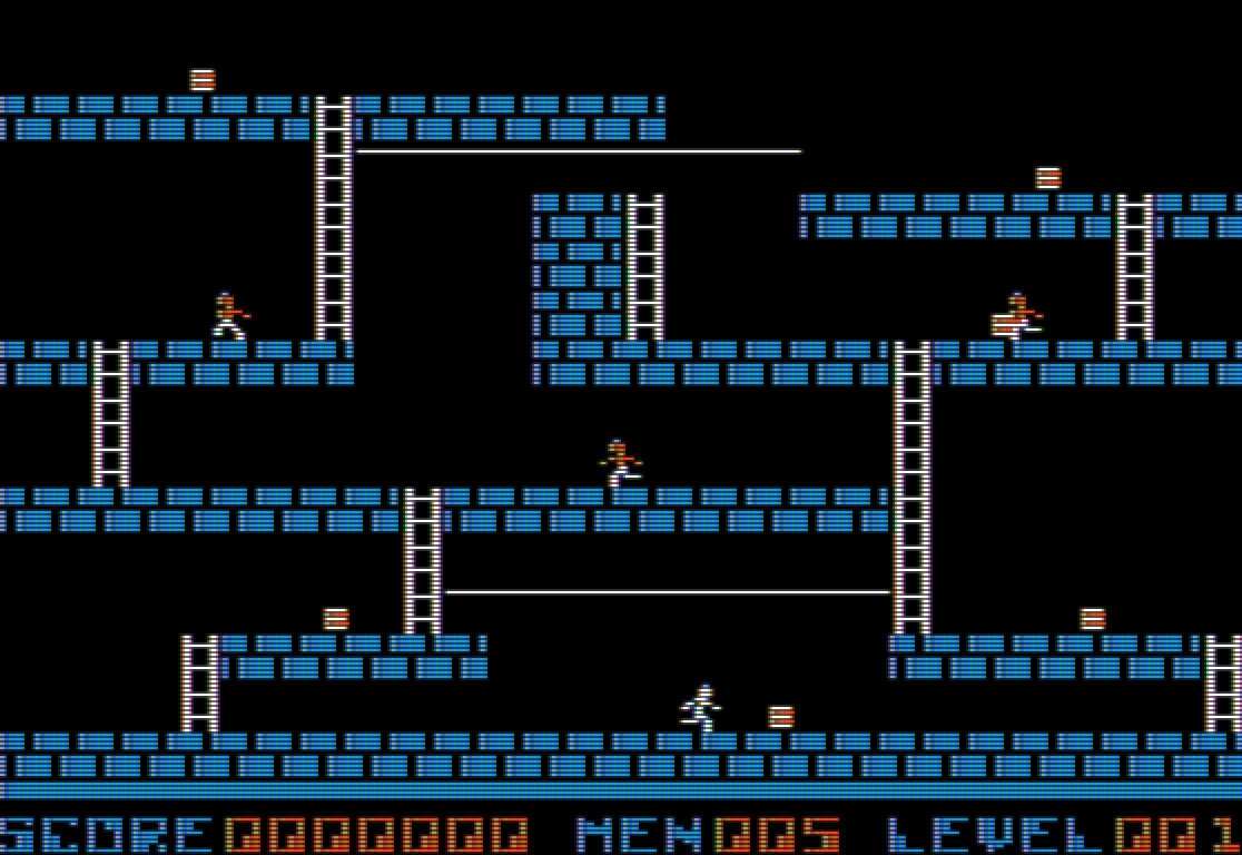
The score is always put on the screen at row 16 column 5, but only the last 7 digits. Row 16 is the status line, as can be seen at the bottom of this screenshot.
There's a routine to add a 4-digit BCD number to the score and then update it on the screen.
    ORG     $7A92
ADD_AND_UPDATE_SCORE:
    SUBROUTINE
    ; Enter routine with A set to BCD tens/units and
    ; Y set to BCD thousands/hundreds.

    CLC
    SED                         ; Turn on BCD addition mode.
    ADC     SCORE
    STA     SCORE
    TYA
    ADC     SCORE+1
    STA     SCORE+1
    LDA     #$00
    ADC     SCORE+2
    STA     SCORE+2
    LDA     #$00
    ADC     SCORE+3
    STA     SCORE+3             ; SCORE += param
    CLD                         ; Turn off BCD addition mode.

    LDA     #5
    STA     GAME_COLNUM
    LDA     #16
    STA     GAME_ROWNUM

    LDA     SCORE+3
    JSR     BCD_TO_DECIMAL2
    LDA     UNITS               ; Note we skipped TENS.
    JSR     PUT_DIGIT

    LDA     SCORE+2
    JSR     BCD_TO_DECIMAL2
    LDA     TENS
    JSR     PUT_DIGIT
    LDA     UNITS
    JSR     PUT_DIGIT

    LDA     SCORE+1
    JSR     BCD_TO_DECIMAL2
    LDA     TENS
    JSR     PUT_DIGIT
    LDA     UNITS
    JSR     PUT_DIGIT

    LDA     SCORE
    JSR     BCD_TO_DECIMAL2
    LDA     TENS
    JSR     PUT_DIGIT
    LDA     UNITS
    JMP     PUT_DIGIT           ; tail call
ADD_AND_UPDATE_SCOREThe other elements in the status line are the number of men (i.e. lives) and the current level.
Here are the routines to put the lives and level number on the status line. Lives starts at column 16, and level number starts at column 25.
    ORG     $7A70
PUT_STATUS_LIVES:
    SUBROUTINE

    LDA     LIVES
    LDX     #16
    ; fallthrough

PUT_STATUS_BYTE:
    SUBROUTINE
    ; Puts the number in A as a three-digit decimal on the screen
    ; at row 16, column X.

    STX     GAME_COLNUM
    JSR     TO_DECIMAL3
    LDA     #16
    STA     GAME_ROWNUM
    LDA     HUNDREDS
    JSR     PUT_DIGIT
    LDA     TENS
    JSR     PUT_DIGIT
    LDA     UNITS
    JMP     PUT_DIGIT           ; tail call

PUT_STATUS_LEVEL:
    SUBROUTINE

    LDA     LEVELNUM
    LDX     #25
    BNE     PUT_STATUS_BYTE     ; Unconditional jump

    ORG     $79AD
PUT_STATUS:
    SUBROUTINE

    JSR     CLEAR_HGR1
    JSR     CLEAR_HGR2

PUT_STATUS_DRAW:
    LDY     #$27
    LDA     DRAW_PAGE
    CMP     #$40
    BEQ     .draw_line_on_page_2

.draw_line_on_page_1:
    LDA     #$AA
    STA     $2350,Y
    STA     $2750,Y
    STA     $2B50,Y
    STA     $2F50,Y
    DEY
    LDA     #$D5
    STA     $2350,Y
    STA     $2750,Y
    STA     $2B50,Y
    STA     $2F50,Y
    DEY
    BPL     .draw_line_on_page_1
    BMI     .end        ; Unconditional

.draw_line_on_page_2:
    LDA     #$AA
    STA     $4350,Y
    STA     $4750,Y
    STA     $4B50,Y
    STA     $4F50,Y
    DEY
    LDA     #$D5
    STA     $4350,Y
    STA     $4750,Y
    STA     $4B50,Y
    STA     $4F50,Y
    DEY
    BPL     .draw_line_on_page_2

.end:
    LDA     #$10
    STA     GAME_ROWNUM
    LDA     #$00
    STA     GAME_COLNUM

    ; "SCORE        MEN    LEVEL   "
    JSR     PUT_STRING
    HEX     D3 C3 CF D2 C5 A0 A0 A0 A0 A0 A0 A0 A0 CD C5 CE
    HEX     A0 A0 A0 A0 CC C5 D6 C5 CC A0 A0 A0 00

    JSR     PUT_STATUS_LIVES
    JSR     PUT_STATUS_LEVEL
    LDA     #$00
    TAY
    JMP     ADD_AND_UPDATE_SCORE        ; tailcall
PUT_STATUS, PUT_STATUS_LEVEL, PUT_STATUS_LIVES